4D tomography
3PBT in glass fiber/epoxy cross-ply. Determination of damage micromechanisms by means of X-ray computed microtomography
XCT has been used to study the onset and development of damage in glass-fiber composite laminates [1]. Notched specimens were loaded in three-point bending. This configuration leads to different stress states in the specimen (tensile stresses and high triaxiality near to the notch tip, compressive stresses under the loading point) and therefore, a variety of damage micromechanisms are activated during loading. Furthermore, the tests are stable and the evolution of damage can be traced up to the last stages of fracture, providing a complete picture of the interaction among the different failure mechanisms.
Fig 1.a) shows a typical load–displacement curve for the 3PBT of notched specimens. The point where the tomographic measurements were carried out are indicated with letters from a to f. Fig. 1.b shows a 3D rendering of the damage pattern measured by XCT. The cracks are plotted in red and three perpendicular planes (YZ, XZ and XY) are shown to identify the notch location and fibers direction in each ply. The 3D crack patterns of the specimens tested at different loads revealed that damage began by formation of intraply cracks in the 90º plies followed by intraply cracking the 0º plies. The evolution of these cracks was also different through the thickness of the laminate. Fiber fracture in front of the notch tip occurred at 65% of the maximum load and finally fiber kinking and interply delamination took place under the loading point.
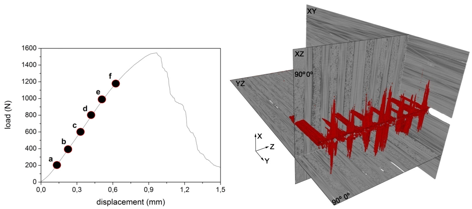
Fig. 1. a) Load–displacement curve of the notched glass-fiber/epoxy cross-ply specimen. The letters (a–f) indicate the six points in which damage was studied using XCT. b) 3D rendering of damage pattern (red) and perpendicular planes from XCT of a sample loaded in three point bending up to 37% of maximum load.
Fig. 2 shows the 3D crack pattern evolution in front of the crack tip at different loads were the described mechanisms are observed. The information within the tomograms allows us to compute some material parameters, e.g. the effective fracture resistance. For that purpose, the total crack area and fiber breakage area (the two main damage mechanisms) were separately quantified, and using the principles of linear fracture mechanics, the effective fracture resistance was obtained (see [1] for more details).
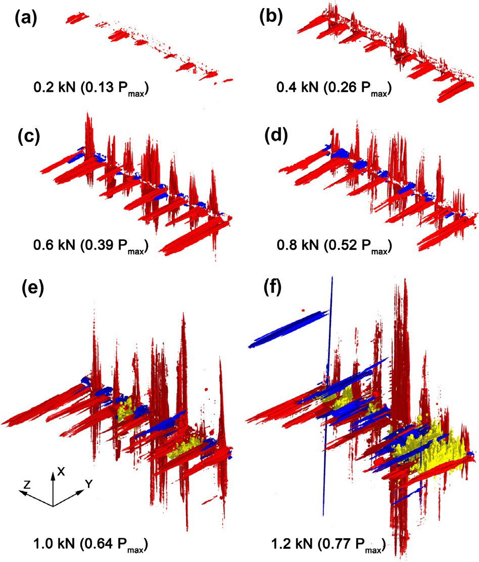
Fig. 2. Tomographic volumes showing the 3D crack pattern emanating from the notch tip in the glass-fiber/epoxy laminate. Primary and secondary intraply cracks are shown in red and blue, respectively. Cracks due to fiber breakage are shown in yellow.
Fig. 3 shows the effective fracture resistance curve of the cross-ply laminate. The values and shape of the effective fracture resistance curves are in very good agreement with the fracture micromechanisms observed by XCT. The curve presents two regions, the low initial one is consistent with the propagation of cracks in the 0º and 90º plies, and similar to values were obtained for unidirectional glass/fiber epoxy composites. The effective fracture resistance increases rapidly as fiber fracture and pull-out start to occur leading the second region. Again the values are consistent with the fracture energy associated to these mechanisms in unidirectional laminates.
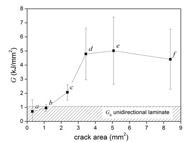
Fig. 3. Effective fracture resistance curve of the glass-fiber/epoxy cross-ply laminate as determined from XCT.
[1] F. Sket, R. Seltzer, J.M. Molina-Aldareguia, C. Gonzalez, J. Llorca. Determination of damage micromechanisms and fracture resistance of glass fiber/epoxy cross-ply laminate by means of X-ray computed microtomography. Compos. Sci. and Tech., 72, 350-359, 2012.
DOI: http://dx.doi.org/10.1016/j.compscitech.2011.11.025